GEOTECHNICAL ENGINEERING1
LUTON
HomeFoundationsRaft/mat foundation design

Raft Foundation Design in Luton – BS EN 1997 Compliant Mat Foundations

Rigorous testing. Clear reporting.

LEARN MORE

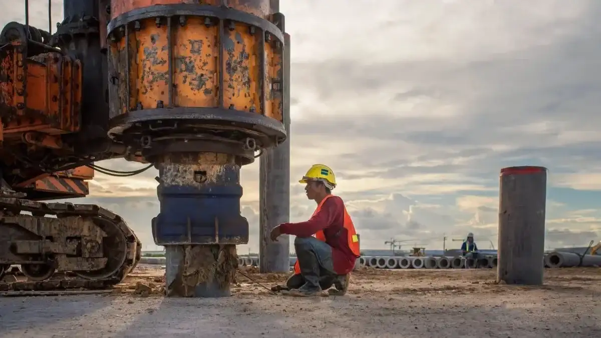
The laser level and total station are the first tools on site for a raft foundation in Luton, but the real work starts with the drilling rig. We mobilise a tracked window sampler rig across the tight urban plots and former brickworks of Bedfordshire to extract continuous disturbed and undisturbed samples. The chalk bedrock under Luton is notoriously variable—the Upper Chalk can be intensely fractured within the top few metres, while the overlying clay-with-flints can shift moisture content sharply between summer and winter. We combine the field data with a CPT test to read the cone resistance and sleeve friction in real time, which tells us where the soft lenses sit before a single cubic metre of concrete is poured. This physical evidence feeds directly into the bearing capacity and settlement analysis required under BS EN 1997-1:2004, ensuring the raft geometry matches the ground, not just architectural loads.

In Luton, a raft designed without accounting for chalk dissolution features can cost three times the original foundation budget in remedial grouting.
Our service areas

Process and scope

Around Luton, from the steep slopes of the Barton Hills to the flatter industrial estates near the airport, we see a common pattern: differential settlement in raft foundations is rarely a uniform consolidation problem. More often it is the result of ignoring the lateral variability in the Lambeth Group sands or the presence of solution features in the chalk. A proper mat foundation design here must account for these sudden stiffness transitions. That's why we specify test pits at discrete locations to log the soil profile visually and to take block samples of the clay-with-flints for laboratory strength testing. The design itself follows the limit state philosophy of Eurocode 7—we check both the ultimate limit state for bearing failure and the serviceability limit state for total and differential settlement. For low-rise residential blocks on marginal ground, we often adjust the raft thickness and reinforcement layout based on a modulus of subgrade reaction derived from plate load tests, not from generic tables. In heavily loaded industrial slabs, we model the raft as a flexible plate on an elastic half-space, integrating the modulus values obtained from our MASW surveys. This approach gives us the bending moment and shear force envelopes needed to detail the reinforcement correctly.
Raft Foundation Design in Luton – BS EN 1997 Compliant Mat Foundations
Technical reference — Luton

Local considerations

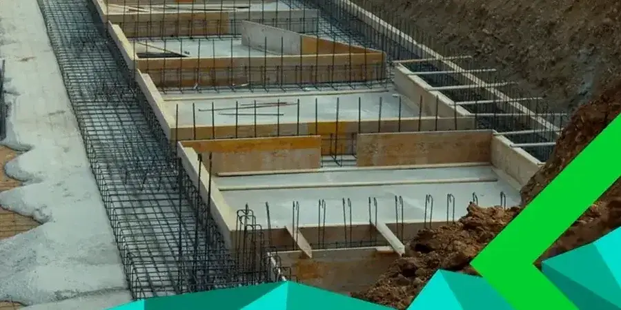
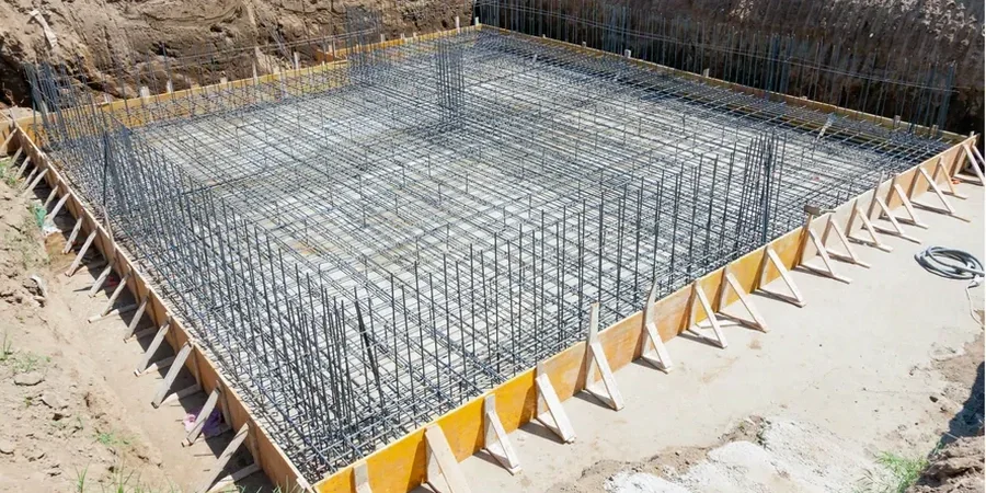
The most frequent mistake we see from groundwork contractors in Luton is treating a raft foundation like a thickened ground-bearing slab and omitting the edge beam. In the clay-with-flints that mantles the chalk across much of the town, seasonal moisture changes cause a shrink-swell zone that can lift the slab edges by 20 mm or more in a wet winter. If the raft does not have a stiffened perimeter beam—or if the reinforcement is placed too close to the soffit—the result is cracking in the superstructure within the first two years. Another classic error is assuming the chalk is competent rock everywhere: solution pipes and swallow holes are common geological hazards in the Chilterns, and an undetected soft infill beneath a raft corner can lead to sudden differential settlement. We mitigate this through targeted grouting of the dissolution features identified in the ground investigation stage, combined with a raft design that includes a nominal structural bridging capability over small voids.

Need a geotechnical assessment?

Reply within 24h.

Email: contact@geotechnical-engineering1.com

Relevant standards

BS EN 1997-1:2004 (Eurocode 7: Geotechnical design – General rules), BS 5930:2015+A1:2020 (Code of practice for ground investigations), BS EN 1992-1-1:2004 (Eurocode 2: Design of concrete structures), BS 1377-9:1990 (Methods of test for soils for civil engineering purposes – In-situ tests)

Technical data

ParameterTypical value
Design standardBS EN 1997-1:2004 (EC7) + UK National Annex
Site investigation referenceBS 5930:2015+A1:2020
Typical raft thickness (residential)250 mm to 450 mm, depending on ground conditions
Typical raft thickness (industrial)500 mm to 1200 mm, reinforced top and bottom
Maximum allowable total settlement50 mm for framed structures (per EC7), often limited to 25 mm
Maximum angular distortion1/500 for brittle finishes, 1/250 for flexible cladding
Subgrade reaction modulus sourcePlate load test (BS 1377-9) or back-calculated from CPT/MASW
Bearing strata in LutonUpper/Middle Chalk, Lambeth Group sands, Glacial Till

Frequently asked questions

What is the difference between a raft foundation and a traditional strip footing in Luton's ground conditions?

A strip footing transfers load linearly under walls, while a raft spreads the entire building load over the full footprint. In Luton, where the chalk is often near the surface but fractured, a raft reduces the bearing pressure to typically 50-80 kN/m², which is well within the safe bearing capacity of even weathered chalk. This avoids the need for deep trench fill in unstable ground and provides a monolithic platform that bridges minor dissolution features.

How do you determine the modulus of subgrade reaction (k-value) for a raft design in Luton?

We do not use generic tables. For Luton sites, we derive the k-value from in-situ plate load tests conducted to BS 1377-9, or we back-calculate it from CPT cone resistance data. For projects where seismic or dynamic loading matters, we also run a MASW survey to get the small-strain shear modulus, which is then corrected for strain level. This gives a site-specific k-value that reflects the actual chalk and till stiffness under the raft footprint.

What is the typical cost range for a raft foundation design package in Luton?

For a residential or light commercial project in Luton, the design package (interpretative report, bearing capacity and settlement analysis, reinforcement drawings, and construction specification) typically ranges from £730 to £3,190, depending on the complexity of the ground conditions and the building geometry. The fee covers the geotechnical design only; site investigation costs are separate.

How does Eurocode 7 affect the raft foundation design process?

Eurocode 7 (BS EN 1997-1:2004) mandates a limit state design approach. We must demonstrate that the ground can support the raft without bearing failure (ULS) and that settlements remain within acceptable limits for the structure (SLS). The UK National Annex specifies the partial factors for actions and material properties. Our designs explicitly present these checks, and we define the characteristic and design values of the chalk and till parameters used in the analysis.

Can a raft foundation be designed on a sloped site in Luton, near the Barton Hills for example?

Yes, but it requires a stepped raft or a raft with integrated ground beams to handle the transition. On slopes typical of the Barton Hills area, we combine the raft design with a slope stability assessment to ensure the overall stability of the cut-and-fill platform. The raft itself is designed to resist the horizontal thrust from the retained ground and to prevent differential settlement across the step in the founding level.

Location and service area

We serve projects in Luton and surrounding areas.

View larger map