GEOTECHNICAL ENGINEERING1
LUTON
HomeGeophysicsSeismic tomography (refraction/reflection)

Seismic Refraction & Reflection Tomography in Luton

Rigorous testing. Clear reporting.

LEARN MORE

Overlooking the chalk bedrock variability across Luton leads straight to foundation surprises that no contractor wants to face. The Cretaceous chalk formations underlying the town, particularly the Lewes Nodular and Seaford Chalk, are riddled with solution features, buried hollows, and variable weathering grades that a standard borehole can easily miss between two points. Seismic refraction and reflection tomography maps these lateral changes in stiffness and depth to competent rock, providing a continuous subsurface image rather than isolated point data. We run survey lines that have flagged dissolution pipes exceeding four metres in diameter near the source of the River Lea, where the chalk-Reading Beds interface creates abrupt velocity contrasts. When the ground model needs to resolve overburden thickness, fracture density, or the top of chalk with engineering precision, this method delivers the geophysical section that a CPT test alone cannot interpolate with the same spatial resolution.

A continuous velocity cross-section across Luton's chalk terrain reveals dissolution features that boreholes spaced 20 metres apart would miss entirely.
Our service areas

Process and scope

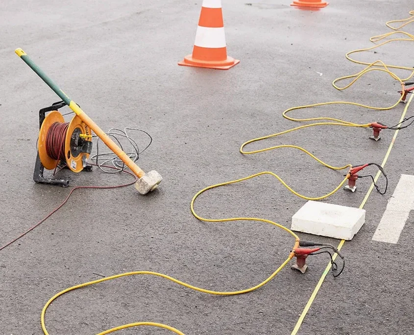
In Luton, we often see that the Upper Chalk weathers to a soft, putty-like consistency that geophones detect as a sharp low-velocity layer, but only if the geophone spacing is tight enough—typically two metres or less. Our field crew configures 24- or 48-channel spread arrays with a sledgehammer source for shallow targets to around 30 metres, and switches to accelerated weight drop when penetration beyond 60 metres is required beneath industrial estates near the M1 corridor. The resulting P-wave tomograms deliver a two-dimensional velocity model where we can distinguish between Grade III chalk at roughly 1,200 m/s and Grade I/II chalk exceeding 2,100 m/s. For deeper structural imaging or mapping the sub-Chalk Palaeozoic floor, where reflection surveys become the appropriate tool, we deploy high-frequency geophones and process the CDP gathers through standard NMO correction and migration workflows. This dataset often complements a seismic refraction baseline profile when the project demands both shallow rippability assessment and deeper stratigraphic control.
Seismic Refraction & Reflection Tomography in Luton
Technical reference — Luton

Local considerations

Luton sits at the northern edge of the Chilterns dip slope, where the transition from chalk to the overlying clay-with-flints and glacial till creates a two-layer velocity model that seismic refraction easily resolves—but only if the survey line is long enough to capture the critical offset from the deeper refractor. Running profiles that are too short is the single most common mistake we correct on sites near the Galley Hill escarpment, where the chalk surface drops by over 15 metres across a single housing plot. Reflection surveys face a different risk: the dry, fractured chalk in summer months attenuates high-frequency energy rapidly, degrading the resolution of deeper reflectors unless we compensate with tighter shot spacing and post-stack deconvolution. Both methods also demand careful coupling of geophones on asphalt or compacted hardstanding, a condition typical of Luton's industrial estates around Kingsway and Airport Way, where we spike through the tarmac or use plaster-bonded base plates to maintain signal fidelity.

Need a geotechnical assessment?

Reply within 24h.

Email: contact@geotechnical-engineering1.com

Relevant standards

BS 5930:2015+A1:2020 – Code of practice for ground investigations, BS EN 1997-2:2007 (Eurocode 7) – Ground investigation and testing, BS 7022:1988 – Guide for geophysical logging of boreholes for hydrogeological purposes, ASTM D5777-18 – Standard Guide for Using the Seismic Refraction Method (referenced where UK guidance is silent on processing workflows)

Technical data

ParameterTypical value
Typical survey depth (refraction)5 to 60 m, depending on spread length and source energy
Typical survey depth (reflection)20 to >200 m, controlled by geophone frequency and fold
Geophone spacing1 to 5 m for high-resolution; 5 to 10 m for regional profiles
Source types deployedSledgehammer, accelerated weight drop, Buffalo gun, or seismic shotgun
P-wave velocity in Grade I/II Chalk>2,100 m/s (competent rock)
P-wave velocity in weathered/putty chalk800 to 1,200 m/s (Grade III–IV)
Data format deliverablesSEG-Y, DXF cross-sections, velocity tomograms in Surfer or ASCII grids

Frequently asked questions

What depth can seismic refraction reach in Luton's chalk geology?

With a standard 115-metre spread and accelerated weight drop source, we routinely image the top of competent chalk and any intermediate refractors down to roughly 40 to 50 metres. For targets deeper than 60 metres, we extend the spread length or switch to seismic reflection, which does not suffer from the hidden-layer limitation that affects refraction in gradational weathering profiles.

How much does a seismic tomography survey cost for a typical Luton site?

A single refraction line of 115 metres with 24 geophones typically falls between £2.340 and £3.670, depending on the number of shot points, surface conditions, and whether we need to close roads or work within restricted hours near residential areas. Reflection surveys cost more due to the denser shot spacing and longer processing time.

Can you run seismic lines on hardstanding or asphalt surfaces?

Yes, and we do it regularly on Luton's industrial estates. We use a Hilti drill to spike through the tarmac for geophone coupling, or plaster-bonded base plates when the surface cannot be penetrated. On compacted crushed-concrete hardstanding, we check coupling with a tap test on every channel before firing the first shot.

What is the difference between refraction and reflection for a foundation investigation?

Refraction gives you a continuous velocity model of the shallow subsurface—ideal for mapping overburden thickness and rippability of the chalk. Reflection images deeper layering and structural features such as faults or the sub-chalk unconformity, but it requires more intensive processing. We often recommend starting with refraction for typical foundation depths, then adding reflection if the chalk surface shows unexpected relief or suspected dissolution features.

Location and service area

We serve projects in Luton and surrounding areas.

View larger map